X-RAY TELEVISION SYSTEMS CRITERIA FOR SELECTION
category: articlesThe article is devoted to criteria of selection of a radioscopic system from a customer.s point of view. The majority of the systems. characteristics and their correlation with the quality of the component parts are described. Exhaustive recommendations for the selection of the necessary radioscopic system, and concise ones for a high-voltage generator and an x-ray tube are given. The article includes types of image enhancement systems and their basic parameters. A purchaser can also find rough price ranges for radioscopic systems.
The application of X-ray television systems is economically justified in comparison with X-ray radiography because of the renunciation of expensive X-ray film use and significant reduction in testing time. On the domestic market there is a rather big variety of X-ray television systems from different producers. Sometimes, it is very difficult to make a chose as all the systems are very closed by characteristics declared. Often the producer advertises the parameters in which he succeeded the best. Frequently, these parameters are not at all important for any specific task or, vice versa, the parameter which is important indeed, hides in every way, or instead of it other parameters are given that imply from it indirectly but don’t have any direct relation with it.
However, every X-ray television system possesses some parameters, looking at which it is possible to make definite conclusion about quality of given system. I would try to make a brief overview of all parameters, analyzing the influence of each parameter on the quality of image obtained.
This article has no target to give the overview of existing X-ray television systems, moreover any specific systems would not be even mentioned here, on the contrary this article attempts to describe all necessary parameters, so that the potential user could decide himself and make independent choice.
There are several main types of X-ray television systems, notable for the operation principle of converting-intensifying link elements. The standard X-ray television system consists of X-ray radiation source, X-ray-optical converting unit and visualization system. The attention would be focused on two parts of the system: X-ray-optical converting unit and image visualization system.
We assumed that the X-ray radiation source is already available at the client. If not, look at the section “EXTRAVOLT” on the site www.testron.ru.
So, let’s start by X-ray-optical converting unit. Main task of this unit – convert the coming-in radiation into the optical image that further would be fixed by receiving camera and converted into the electrical signal, that goes to the system of image visualization. Similar converting units could be based on several principles. Let’s consider their advantages and disadvantages.
Type 1. X-ray-optical converting units based on scintillation crystal or fluorescent screen.
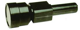 Usually the converters are arranged as follows: At the inlet the scintillator, converting the X-ray radiation into visible light is installed. From its reverse side the high-sensitivity camera reads the optical image. The standard isocon (X-ray TV system “INTROSCOPE”), or superorthicon, combined with optical amplifier (X-ray TV system «РИ-60 ТЭ»), or high-sensitivity ССD camera (X-ray TV system «УРИ-10ПЗС») could be used as camera. The disadvantages of this type of converting units are rather obvious. Due to the low coefficient of X-ray radiation conversion into the light it is necessary to increase the radiation dose at the inlet of converting unit. It has to reduce the distance from the tube to the crystal and strongly increase the power, i.e. increase the anode current of the tube. The use of X-ray high loading tubes that have a big size of focal spot accordingly results in the deterioration of spatial system resolution: bigger focal spot is, lower the resolution is. Unfortunately, it is impossible to gather this problem from leaflets as when defining the resolution the reference standard is put directly onto the inlet screen, and the focal spot size of the tube does not have any negative influence on the result obtained. In real conditions the piece is at a certain distance from the converting unit, and the increase of focal spot drastically deteriorates the system parameters. In addition, such systems have rather low contrast. This relates to that it has to use the high-sensitivity camera which possesses low ratio “signal – noise”. The sensitivity of testing as per GOST 7512-82 makes, for example, 3 - 4 % for X-ray TV system “INTROSCOPE” and «РИ-60ТЭ» at the tested steel thickness of up to 20 and 45mm respectively. It is also important that the increase of X-ray unit loading results in the deterioration of radiation environment at the working place and, consequently, to the increase of the costs on the protection against the radiation as well as to the decrease of X-ray tube service life. It has to consider as advantage of similar converting units the possibility of their using in case of high-energy radiations (tens of Megavolts) because of the scintillator thickness increase, in particular, when using betatrons for the radiographic inspection of steel about 100mm thick. These converting units are capable to withstand high radiation loads over a long period of time without overlapping by a piece or safety screens.
Тип 2. Преобразователь на основе вакуумного усилителя яркости рентгеновского изображения - так называемый РЭОП.
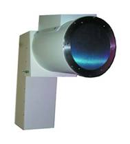 In this unit its inlet screen is an element of vacuum system, applying the method of electrostatic electron transfer by high-voltage accelerating electrodes to the outlet luminescent screen. The image generation occurs already on the screen of small size – approx. 25 mm. Due to the electrostatic intensification the image on the outlet screen is very intensive even at the extremely low anode current. In particular, many similar converting units begin to operate since 6 kV at the anode current of only 0,5 mA. The high illumination and small size of outlet screen allow the use of the mirror to reflect the image at the angle of 90° without practically any noise and due to this to move the ССD matrix of receiving camera from under the action of X-ray radiation beam and to improve the noise characteristics. Besides, the high illumination of outlet screen allows the use of receiving ССD camera of low sensitivity with very high ratio “signal – noise”. As a result the contrast sensitivity and resolution of the system increase. According to GOST 7512-82 the sensitivity of similar systems makes up 0,7 - 2 % at the thickness of steel under inspection up to 102mm. The systems with REOP have the modes of electronic-optical intensification which are preset by switching over the high voltage values on the electrodes; the image being focused on the outlet window only from part of inlet window; so, the system resolution increases. These particular features ensure the high quality of the image, reducing the fatigability of the operator. It has to consider as disadvantage of similar systems their sensitivity to shakings and impacts which makes difficult their application in mobile X-ray television systems.
Тип 3. Твердотельный преобразователь на основе аморфного кремния
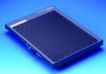 Solid converting units have higher resolution and dynamic range in comparison with REOP. In addition, their size is small and they could be used in mobile X-ray television systems. Unfortunately, at date the cost of solid converting units is significantly higher than the cost of REOP. It has also to note that many solid converting units (especially those of big size) have the value of contrast sensitivity about 2-2.5% which is inferior to REOP, having this parameter at the level of 1-1.25%.
From the point of view of price and quality the optimized version is cheap converting units FILIN 1010L (100x100mm), FILIN 2010L (200x100mm) and FILIN 2020L (200x200mm) with contrast sensitivity parameter of about 1%. To date they are the real alternative to small 6-inch and 9-inch REOP.
However, now in the industry the most called-for are the systems, based on REOP; therefore, further we would consider the characteristics of such systems.
Thus, first parameter of the systems with REOP – is the type of REOP.
Actually on Russian market there are only imported REOP of companies SIEMENS and THALES. They are rather similar by their parameters, however, the company THALES offers special REOP with non-burnout exit window. Differing from ordinary ones they are capable to withstand over the longer period the direct unshielded radiation. Therefore I’d recommend the use of the systems with REOP from company THOMSON.
It has to point out that to reduce the cost price of X-ray television systems many companies use cheaper medicals REOP. These REOP have a little higher sensitivity which allows the compensation of cheap camera and low quality of the optics, installed in the system. Unfortunately, medical REOP are not designed for the long impact of the radiation and fail much quicker.
Now, let’s pass to the next parameter – geometrical resolution of the system.
This parameter is determined by several components. First of all, this is the REOP resolution. Most part of the companies indicates the REOP resolution and somewhere in small footnotes write that it was measured by microscope at the exit window. Of course, this example is interesting from the scientific point of view, but it is out of all relation to the real resolution of X-ray television systems, as this value is high and never could be achieved during the transfer of images through the optical channel and receiving camera. The final resolution of the system depends on the quality and efficiency of the optics, on the type of receiving camera and image visualization system. The output resolution of REOP usually makes up 4.5 – 8.0 lp/mm. Then, optics goes. In order to keep this resolution at rather low aberrations on the image edges, it is necessary to use the optics, having the optical efficiency of at least 2.8. In cheap systems the optics with optical efficiency of 3.5 – 4.5 (in 2 - 3 times cheaper) is often used, which results in the quality of image. Now the most popular are CCD cameras that substituted obsolete vidicons. The final resolution of X-ray television systems depends on the number of pixels of the camera. Whatever the REOP outlet screen resolution would be, the number of transferred image points would be limited with number of the pixels of receiving camera. Average analogue CCD camera has the matrix size of 758 x 582 pixels. To get theoretical limiting resolution of the system in lp/mm, the dimension of inlet screen should be divided on double quantity of camera pixels (in order to get the number of line pairs, but not simple lines). In fact the resolution would be much lower because the geometrical resolution of CCD camera can’t be equal to the number of pixels; it is always a little worse – on 10-15%. Let’s make the simple calculation. If the inlet window has the size of 215 mm (standard size for REOP of 9” in diameter), then when using the standard camera we get the parameters of theoretically limiting geometrical resolution - horizontally (785 pixels/215 mm)/2 = 1,83 lp/mm, vertically (582/215 mm)/2 = 1,35 lp/mm. It is pity, but this is fact. Of course this calculation is primitive. In reality everything is much more complicated, but anyway you would not get better result. Now, look at the leaflets – interesting, isn’t it?
Some companies use in their systems more expensive digital cameras, having 1024 x 1024 image point and more. In this case the figures are more attractive – for example, the limiting geometrical resolution of 9” REOP would make up 2.4 lp/mm both horizontally and vertically, which is already much better.
Third parameter – type of camera used.
The cost of CCD camera varies from hundreds to tens thousands USD, and in good systems it represents a significant part of their cost price. Accordingly, the wish appears to purchase cheaper camera. How distinguish the good camera from the bad one as finally just the camera determines the final parameters of the system? The simplest way is to ask the equipment producer about physical size of the CCD camera matrix. Bigger it is, better is (at the similar quantity of camera pixels). Cheap cameras have the matrix size of 1/4 or 1/3 inch (which is used in amateur’s video cameras). Cameras with matrix size of ½” are of higher quality. Generally, it would be more correct to talk not about the size of CD matrix but about the size of its pixels. But usually producers don’t know this information.
In X-ray television systems it is admissible to use CCD cameras with matrix size of ½” or higher for matrixes with about 750x580 pixels and 2/3” and higher for matrixes with about 1000x1000 pixels. Bigger size of ССD matrix is, the thermal and X-ray noises of the matrix are lower due to the higher number of pixels; vice versa, the signal level from every pixel being much higher. Matrixes of big size have much better ratio “signal – noise”; just this ratio finally influences both the resolution and the contrast sensitivity of the system.
Some cameras have an integrated system of marginal sharpness intensification, which results in significant improvement of the image quality. The best systems use digital cameras of high resolution with matrix sizes of 1 inch and more. In this case, pay attention to the type of output signal. Some companies, even when using digital; cameras transfer the information by ordinary video signal. The standard of video signal was developed years ago and it was not designed for the use of digital video cameras. So, even if the camera’s resolution make up 1024 x 1024 and higher, when transferring the image through the video signal the quality of final image would be considerably worse than at the compete digital transfer. The systems with compete digital transfer have digital cross cable from the camera to the computer and it is rather difficult to confuse it with video cable.
Some small additional information for those who intends to use the system for the inspection of objects in real time (i.e. without stopping the object before the inlet window of REOP): Purchase only those systems, in which the progressive scanning camera is installed, as it provides the minimum image deformation in comparison with cameras of standard interlacing. When using the interlacing the image consists of two semi-frames; if one of them transfers even lines of the image, another one – uneven. If during the transfer the object under examination would be displaced the quality of image would drastically drop. Cameras of progressive scanning transfer the image line by line, so they don’t have such a problem.
Fourth parameter – availability of the system to turn the camera.
This system allows the turning of receiving chamber during the work so that the image under examination would be optimally positioned in respect of the camera pixels and direction of scansion. This helps a lot when detecting fine cracks as if this crack gets between the lines or between image scans, it would be very bad visible or invisible at all. The second advantage of this system consists in that it allows the image visible zone increase. As the matrix is square or rectangular and the inlet REOP screen is round, then in case of examination of the weld, for example, you would see on the screen the maximum possible zone of the weld if it is positioned bias the CCD matrix. The system to turn the camera gives you such possibility.
Next parameter – type of the image visualization system
Traditional TV monitor would not be the best choice as the image on it blinks rather distinctly (with frequency of 50 Hz), which significantly deteriorates the quality of perception and fatigues the operator. More correct would be the selection of TV monitor with image sweep of 100 Hz. However, its parameters are far to be ideal. In case of need in obtaining a really quality image it has to add the system of image improvement to the TV monitor. In X-ray television systems, using the digital cameras, the system of image improvement is their integrated part, and the use of TV monitors in them is not possible.
Sixth parameter – visual resolution of X-ray television system.
It shouldn’t confuse the visual resolution with geometrical one: the visual resolution is defined by special mira in form of lead plaque with grooves, setting certain amount of line pairs per mm. The mira is fixed at the inlet REOP window at the angle of 45° relatively to the sweep lines of the monitor and to the lines of CCD matrix points. 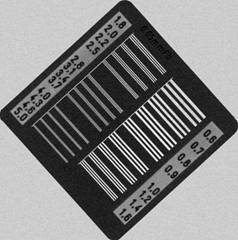 The resolution at which it is possible to see the alternation of black and white lines is considered to be the real visible resolution of X-ray television system. Special attention should be paid to that the mira has to be fixed directly to the inlet window of REOP, i.e. the geometrical amplification is not used. Many companies indicate the parameters of resolution and contrast sensitivity at a certain geometrical amplification. This is when the test-object is fixed at a certain distance from REOP and because of purely geometrical amplification (e.g. in two times) the band of 0.1 mm is projected to the REOP as band of 0.2mm; it means on such way it is possible to increase the resolution in two, three and more times; the real size of visible image on the screen being reduced in inversed proportion to the geometrical amplification. Don’t confuse the geometrical amplification with optic amplification of REOP. Usually, if REOP has several modes of optic amplification then the parameters of visual resolution of the system for every mode are given. Strangely enough, but the visual resolution of the system could be higher than the geometrical one. Partly this happens because of that the mira position at not exact angle of 45° to the lines of CCD matrix is optimal from the point of view of visual resolution. The situation when the bars could fall exactly between the points is practically excluded. It also has to take into consideration that man is prone to see what doesn’t really exists, particularly when he knows what he has to see. The visual resolution is strongly increased when using the filter “Sharpen” in the system of the image improvement. From the point of you of the radiographer the parameter of visual resolution of the system is one of the most important as just this parameter determines the visibility of flaws on the screen of monitor.
And, finally, the most important from all parameters under consideration – contrast sensitivity.
It is defined as relation of wire thickness to the thickness of metal on which the measurement takes place. It means, if on the metal 50 mm thick the wire 0.5mm thick is visible its contrast sensitivity makes up 0,5/50 x 100 = 1 %. Less is this value, higher is the quality of the system. In most cases the contrast sensitivity of X-ray television systems is required to be better than 2%. Usually, the X-ray television system provides high results at the inspection of medium thickness – from 5 to 70mm of steel. If the thickness is less the sensitivity decreases, which is explained by decay of frequency-contrast REOP sensitivity and radiation blur that becomes comparable with sizes of small details of the image. Within the range of big thicknesses the sensitivity also becomes a little worse, as the dissipation of radiation within the material thickness increases. The sensitivity of the control sharply increases if there is a system of image improvement as the integration completely removes spatially de-correlated noises, reducing the contrast sensitivity. Like when defining the visual resolution it has to pay attention to the absence of geometrical amplification as many companies give the sensitivity curves at the geometrical amplification in 2-6 times in order to improve the characteristics of their systems in the field of small thicknesses. The question could raise, why the most important parameters are considered at the very end?

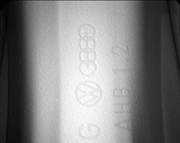
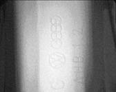
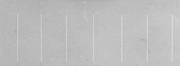 It is strange but just these parameters are the most illusory. The visual resolution and sensitivity of the control are influenced by combination of correlated physical factors: type of X-ray unit and X-ray tube used; size of focal spot; anode current pulsation coefficient; energy and intensity of radiation; thickness of material and configuration of the object; external illumination of the screen; electro-magnetic interferences etc. Often the parameters, obtained in ideal conditions of the plant-fabricator and used in the advertising are completely unachievable in real operation conditions. Among all other issues at the definition of visual parameters one of the determining factor consists in the level of professional level of radiographers-operators and absence of sight problems at them. Let’s consider an example: In front of you there is a picture of wire penetrator. Look, how many wires you see. Below there is an image, subjected to the processing with complicated mathematical algorithm of sensitivity definition. Now you could see how many wires the computer seen.
So, the conventional method of visual parameters definition could not be considered objective. However, the application of high-quality components in the system guarantees the highest quality of image obtained and high values of visual resolution and control sensitivity, accordingly. That’s why we first discussed the types of REOP, cameras, optics and only after this – the parameters of the system.
The parameters of X-ray television system could be significantly improved by using the system of image improvement. Main purposes of these systems are digitization, integration, mathematical processing, visualization and archiving of the images.
Main parameter of the systems of image improvement is the bitness of input signal digitization.
 |
 |
 |
 |
 |
 |
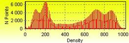
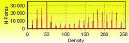
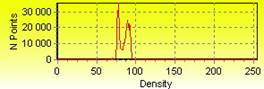
The majority of the systems of image improvement digitize the input signal of 8 bits which makes up 256 gradations of gray color. Similar systems are morally obsolete. To get the high-quality image it is necessary to digitize the signal with, at least, 10-bit converting unit, which makes up 1024 gradations of gray color. If look at the bar chart one could notice that the image under examination is within rather small zone. If the image under examination occupies one quarter of potential bar chart width, then at the digitization of input signal of 8 bits inside the zone under examination there are, in fact, only 64 gradations of grey color. To get the optimum quality of the image this zone should be extended on the whole possible width of bar chart, but in this case we would observe rather big notches in the bar chart, and the image on the screen would be too noised with abrupt changeover from one gradation to another. From the other side, if at the same mode the 10-bit camera and digitization system are used, we would have at the same zone not 64 gradations of gray, but 256. When extending this zone within the whole dynamic range we would get the fade and quality image. Thus, when selecting the system of image improvement, aim to get the signal digitization of at least 10 bits. Many companies in their leaflets hide the real bitness of the system, confining themselves of phrases that the complete software is of 16 bits and the bitness makes up 8/16 bits etc. In digital cameras the digitization system is directly inside the camera, and from the system of image improvement it is required only to manage with images, containing more than 8-bit information.
The simplest way of system bitness definition is to look at the bar chart of the image. If on the horizontal axis the values from 0 to 255 are laid out, the system is of 8 bits; if values are from 0 to 1024 – the system is of 10 bits etc. Multi-bit systems, allowing the management with practically any digitization bitnesses, give the values on horizontal axis in %.This presents to the user the unified interface which doesn’t depend on the equipment applied.
Other functions are present in most part of the system in one form or another; I would talk about them in arbitrary order.
Integration
The integration by 16 or 32 frames is usually used to reduce the noise; however it is preferable that the system would have the possibility to integrate up to 256 frames. If you intend to work with images in movement, I recommend you to choose the system in which so-called recursive integrating filter is available. Differing from traditional integration systems, this filter, keeping the speed of 25 frames per second, shows the integrated image by last N frames. When the recursive filter is used the image moves on the screen smoothly, without jerks even at relatively high values of N.
Digital filters
Modern systems have big set of digital filters. In fact, you would use three-four filters only (of course, I don’t mean research laboratories). It is desirable that the system would have an wave filter, type “sombrero”, filters of low and high spatial frequencies, filter «Sharpen» to intensify the sharpness and one or two pseudo-color filters. Color filters are especially actual for 10- and 12-bit systems. As usual compatible personal computers can’t reproduce on the screen more than 8 bits of one color, to display bigger quantity of gradations different color ranges are used. If you intend to work in real time the filters should also have the possibility to operate in real time.
Work with bar chart
The system should be able to show the bar chart both for the whole frame and for the brightness within the dedicated zone of the image. It is necessary to have the possibility of changing the bar chart form. Good systems are able to show the bar chart in real time with the speed of the moving image. When drawing the brightness bar chart it is necessary to provide for the possibility of measuring the distance directly on the bar chart, which allows rather accurate measurement of the flaw size. It is also preferable that the system supported the table of digital density conversion system, providing the set-up of bar chart ramp before its digitization. Such table has to be present in 8-bit system as it allows getting rid of 8-bit system disadvantages by method of brand spread of bar chart at the level of analogue system.
Measurement of distances
The system should provide the measurement of the distance between any two points, both directly on the screen, and on the brightnes bar chart. It is also preferable that there would be the possibility to magnify the image using the magnifying glass and to fulfill the measurement on the image magnified.
Database available
Many systems don’t have any database (or it is separately sold), and the unique possibility for them is to record the image into the graphical file on the disk. This is, may be, acceptable for the research laboratory but absolutely inadmissible in conditions of an enterprise where during the shift there could be hundreds or thousands of images. The database should be capable to store images with detailed description of every one of them and to quickly find the necessary image among the entire database, including that stored on magneto-optic and DVD disks. The automatic file backup of database and the robustness of database in respect with computer failures must be provided for, as the loss of database for the whole working day due to the computer failure is equal to return all objects back to the repeated inspection. Ask from the company-seller whether it undertakes to finalize the interface of database especially according to your requirements.
Processing at the alarm situations
It is preferable that the system of image improvement would have a link with high-voltage generator for the instantaneous switching off the high voltage in case of excessive overexposure of the X-ray-optic converting unit. This would prolong the service life of your system.
Control of peripheral units
It is preferable that the system would have a hardware and software interfaces for the control of different peripheral units, like collimating diaphragm or X-ray protecting shutters, that protect REOP from excessive overexposure. The most developed systems are provided with the possibility to control of different manipulators.
March, 2007
B.Y. Kramer
Author’ remark
The initial text of the article is taken from the book (In the World of NK” N4 December, 2000 and revised a little in accordance with actual level of X-ray television systems development. In spite of this revision, this article is, of course, a little obsolete and under-reflect modern tendencies. However, the common principles, stated in the article remain unchanged as they re based on common laws of physics.